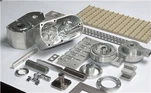
How to Choose the RIGHT Fixture / Jig (工装夹治具)
Clarify the "input file" of the work-piece
Geometry: overall size, 3-D shape, wall thickness, number of set-ups
Tolerance & surface finish: the fixture must contribute ≤ 30 % of the total process error budget
Batch size & takt time: prototype → modular or 3-D printed; high volume → dedicated hardened steel
Select locating method BEFORE clamping method
Use "3-2-1" or "one-plane + two holes" to constrain six degrees of freedom; location pins and rest pads should be adjustable or replaceable for wear compensation
Perform a locating-error calculation: Δloc = f (datum shift + pin clearance + part variation). If Δloc > 1/3 part tolerance, redesign the datum scheme
Choose clamping force that is "just enough"
Rule of thumb: Fclamp ≈ 3 × cutting force in the weakest direction
For aluminium or thin-walled parts use low-force toggle, pneumatic (0.4–0.6 MPa) or hydraulic (2–4 MPa) clamps to avoid distortion; for heavy steel forgings use high-power hydraulic swing cylinders
Always align the clamping vector with the locating plane to minimize bending moment
Check fixture stiffness against cutting force spectrum
Minimum natural frequency f n ≥ 300 Hz for high-speed machining; add ribs or box structure if modal test fails
Static deflection under max load ≤ 0.01 mm at tool tip
Decide on manual, semi-automatic or fully-automatic
Manual: toggle, cam, wedge-cheap, quick for < 500 pcs
Semi-auto: pneumatic with 5/2-way valve-good for 500–10 000 pcs
Fully-auto: zero-point or pull-stud system on HMC-allows 60 s pallet change, economic above 10 000 pcs
Prefer standard parts and modular kits
80 % of functional elements (locating pins, clamps, base grid) should be catalogue items-cuts design time 40 % and cost 25 %
Use aluminium profile for low-mass 3-D printed jigs when cycle < 30 min; switch to hardened 45# or 40Cr when annual volume > 5 000
Evaluate thermal & chip management
Coolant flow path must not push chips under locating pads; add 1–2° sloped surfaces and flush holes
For titanium or CFRP, provide thermal isolation pads to keep part temperature within ±2 °C
Verify quick-change & mistake-proofing features
Color-coded clamps, one-way inserts and RFID tags prevent wrong loading
Replaceable wear inserts should be changeable within 3 min without removing the fixture from the machine
Run an economic analysis
Cfixture ≤ (Cscrap + Crework) saved × pay-back period (usually 6–12 months)
Include cost of storage, maintenance and re-calibration
Document and digitize
Create a fixture passport: 3-D model, bill of materials, clamping sequence, max torque, inspection schedule
Upload to MES so that the same dataset is available for future repeat orders or sister plants
Follow the ten steps above and you will consistently select (or design) a fixture/jig that is accurate, economical and production-ready.